
8.
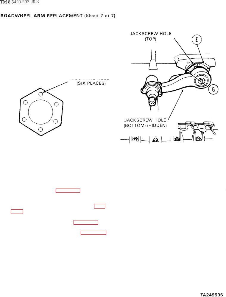
Position retainer (E) so that its jackscrew holes
are at top and bottom of upper spindle.
9.
Using pin punch, aline six mounting holes in
retainer (E) to holes in housing.
Put six lockwashers and screws (G) into
10.
m o u n t i n g holes.
11.
Using crowfoot wrench and torque wrench,
tighten six screws (G) alternately and evenly to
95-125 lb-ft (129-169 N.m).
12.
Connect adjusting link at No. 1 roadwheel
position, if necessary (page 14-59).
Install shock absorbers if roadwheed arms were
13.
removed from positions No. 1, 2, and 6 (page
14.
Install suspension torsion bar (page 14-27).
15.
Install wheel hub if removed (page 14-18).
l n s t a l l roadwheels (page l4-53).
16.
End of Task
14-8