
TM 5-5420-202-20-3
TOP DECK FRAME ASSEMBLY REPLACEMENT (Sheet 4 of 10)
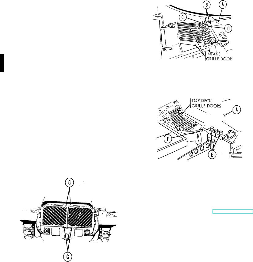
Top Deck Replacement (Sheet 4 of 4)
3.
Using 1-1/8 inch wrench, tighten four bolts (two
each side) (B) securing top deck (A) to front
frame.
4.
Mount two intake grille doors (one on each side)
of top deck.
5.
Using 3/4 inch socket, install two screws (C) and
lockwashers (D) (one each side) securing two
intake grille doors to top deck.
6.
If equipped, install MICLIC support bracket (TM
9-1375-215-14&P). If not, install six screws,
lockwashers, and flat washers (El to top deck
(A).
7.
Using 1-1/2 inch socket, tighten six screws (E).
8.
Close top grille doors (four each side). (TM 5-
5420-202-10).
9.
Using 15/16 inch socket, tighten two locking
screws (F) securing top grille doors.
10.
Close two exhaust grille doors. Using 1-1/8 inch
socket, install four screw assemblies (G) to
secure doors.
11.
Connect holddown cylinder hose assemblies
CV3 and CV4 at manifold (TM 5-5420-22824).
End of Task
U.S. GOVERNMENT PRINTING OFFICE: 1995 646-018/20081
Change 5 15-24