
TM 5-5420-202-20-4
MATERIAL
FABRICATING REQUIREMENT
STOCK
DESCRIPTION
Wire, electrical
M13486/1-3
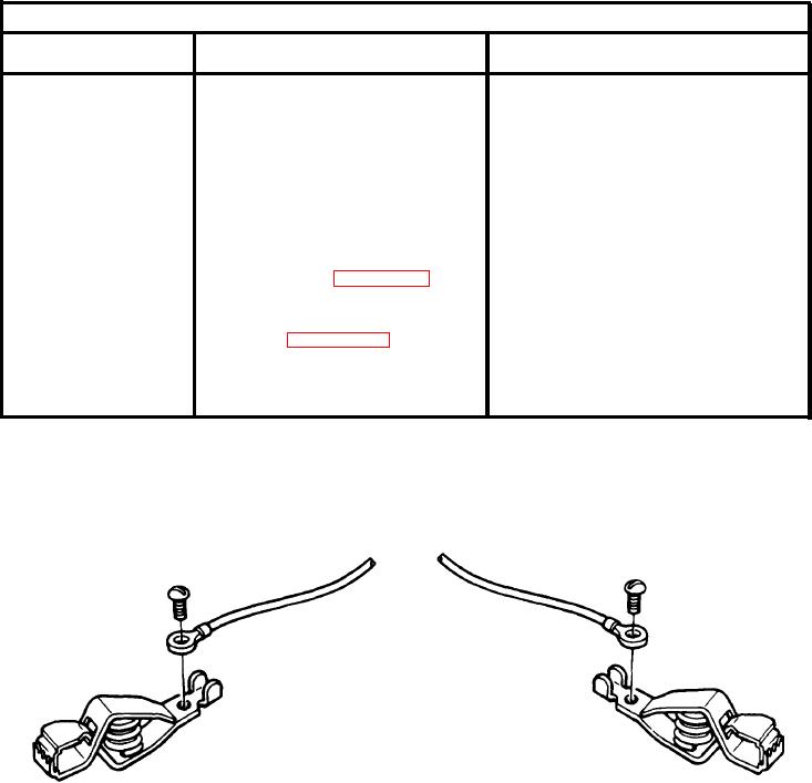
1. Cut heat shrink
16 gage, 3-5 ft. lg
tubing into two equal
lengths and slide onto
W-C-440B Type PC4
Power clip (2 required)
wire.
7056709
Lug Terminal (2 required)
2. Solder lug terminals
to each end of wire.
8/32 UNC-2A X 1/4 lg. Screw (2 required)
3. Connect lug terminals
NSN 3439-00-307-7333 Solder (Item 67, Appendix D)
to power clips with
screws, Bend tabs of
MIL-R-46846, Type V
Heat shrink tubing, 6 in. lg
power clips over wire.
(Item 60, Appendix D)
4. Shrink tubing over ends
of lug terminal and
wire connections.
Figure F-8. Fuel-Water Separator Test Cable
TA248940
F-8