
TM 5-5420-203-14
c. Assembly of the Bridge Separated into Eight Sections - CONT
(15) Positioning of Far-Shore Ramp Sections.
(a) Place four crib timbers in line with the assembled portion of the bridge to support the far-
shore ramp sections.
(b) Position a male ramp section and a female ramp section on the timbers. Leave about 1 ft
separation between the ramp sections and the center sections to connect the hydraulic
hoses.
(16) Installation of Far-Shore Ramp Section Flexible Hydraulic Hoses.
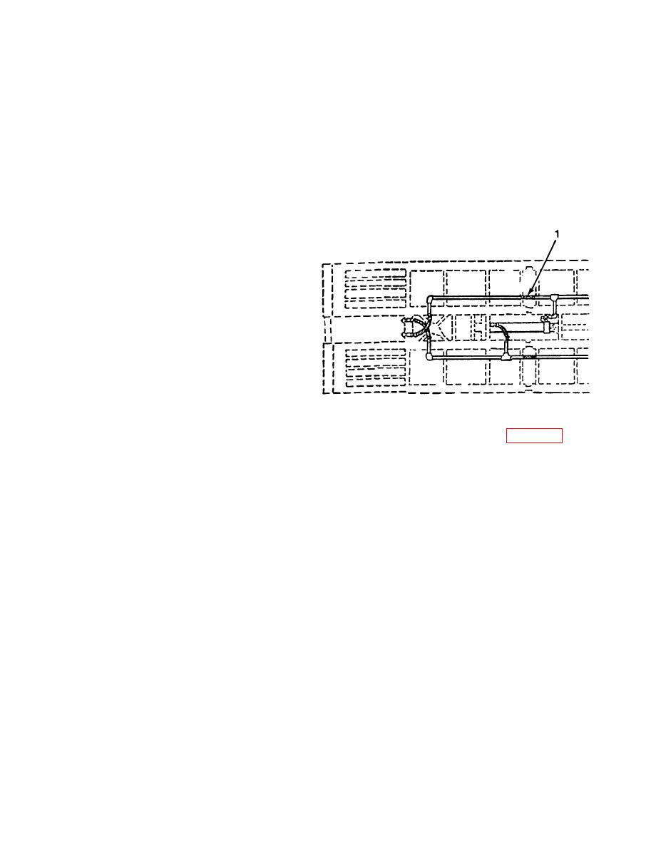
(a) Connect 2 ft 8 in. hydraulic hose
(1) to center section and ramp
section.
(b) Position second ramp section and
aline so an equal distance exists
between both ramp sections,
leaving about 1 ft separation
between ramp section and
adjoining center section.
(c) Position and aline the two ramp
sections so an equal separation
distance is on each end.
(17) Installation of Far-Shore Diaphragm, Lateral, and Transverse Braces. Refer to page 2-24.
(a) Using three bolts (3), attach one end of diaphragm (4) (pintle holes facing toward ramp
end) to clip angle of ramp section (1). Thread three nuts (5) on bolts (3). Tighten bolt/nut
assemblies. Place three retainers (6) in outside holes located on threaded end of three
bolts (3).
(b) Position the clip angle of second ramp section (2) to aline with the diaphragm (4).
(c) Using three bolts (7), attach other end of diaphragm (4) to clip angle of second ramp
section (2). Thread three nuts (8) on bolts (7). Tighten bolt/nut assemblies. Place three
retainers (9) in holes located on threaded end of three bolts (7).
(d) Aline the lateral brace (10) with holes on the bottom flange of the inside girders of ramp
sections (1) and (2). Place four bolts (11 ) through holes with heads to the top as shown.
(e) Tighten bolts (11).
NOTE
The pintles of the transverse braces are threaded. The brace maybe installed on either side
of the clip angles.
(f') Position first transverse brace (12) so holes aline with clip angles on ramp sections (1)
arid (2).
2-23
