ARMY TM 5-5420-212-10-1
MARINE CORPS TM 08676A-10/1-1
c.
Double Story Using Capsill Roller Beam
Double story bridges 2E + 13 thru 2E + 22 bay with and without link reinforcement use a building frame as
described in paragraph 4-5 b., with an additional capsill roller beam, which has rocking rollers to carry the extra weight.
For link reinforced bridges the capsill roller beam is positioned 9 ft (2.7 m) from the A’ peg to provide enough working area
to attach link components. For bridges over 12 bays without reinforcement the capsill roller beam is positioned 3 ft (0.9 m)
minimum from the A’ peg. The drill is as follows:
(1)
Place two double story baseplates either side of the CRB peg approximately 15 ft (4.6 m) apart. These
baseplates will be for the capsill roller beam.
(2)
Put a roller beam adjustable support in each baseplate and hook a building frame cross girder to the
adjustable supports [para. 4-5 b. steps (2) thru. (4)].
(3)
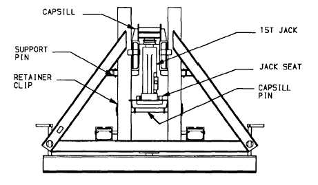
Place a capsill pin in the correct hole of each adjustable support (this hole position is determined by
design) and secure with retainer clips. Place a jack seat over the capsill pin.
(a)
Curved cut-outs fit over capsill pin and open end of U-shaped ridge faces away from bridge
centerline.
(b)
Capsill pin is never used in holes 4, 5 or 6.
(4) Place a support pin in each post of the adjustable support. The support pin must be placed one hole
above the capsill pin, to permit easy installation of hydraulic jack.
(5) Place a capsill roller beam onto the support pins. The capsill must be put in through the top of the
adjustable support posts. Fixed pins prevent sliding the capsill in from the side.
(6)
Place a hydraulic jack (15 ton) on each jack seat.
(a)
Operate hydraulic jack to raise capsill off support pins. -
(b)
Do not remove support pins.
(7)
Place a rocking roller at each end of the capsill.
(a)
Secure rocking roller to capsill with two nose pins.
4-10