ARMY TM 5-5420-212-10-1
MARINE CORPS TM 08676A-10/1-1
(3)
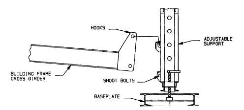
Hook a building frame cross girder onto the adjustable supports. One of the supports may have to be moved
slightly so both ends of the cross girder can be attached.
(4)
Push shoot bolts through each cross girder and support brackets and turn to lock position.
WARNING
If roller beam Is to be set higher than the lowest setting, push captive support pin through each
adjustable support post at proper height. If support pins are used, ensure that they are fully
seated (pushed In) and that the jack seat is fully seated on each pin.
(5)
Place a jack seat over support pins or lower rail in each adjustable support.
(a)
Curved cut-outs fit over pins or rail in bottom of support.
(b)
Open end of U-shaped ridge faces away from centerline.
(c)
Insert retainer clip through support pin.
4-6