ARMY TM 5-5420-212-10-1
MARINE CORPS TM 08676A-10/1-1
(2)
Place roller beam fixed supports in the baseplates.
(3)
Position baseplates under roller beam.
(a)
Ensure that roller beam is located in pivoting head of fixed support.
(b)
Ensure that sloping edge of baseplate faces gap.
(c)
Packing (3 in x 8 in x 36 in) can be used under baseplates if bank conditions are bad.
(4)
Final position roller beam.
(a)
Ensure roller beam is centered over centerline and RB peg.
(b)
Ensure roller beam is at 900 to centerline.
(5)
Lock rollers.
b.
Double Story 2E + 1 thru 2E + 12 bay
Double story bridges (2E + 1 thru 2E + 12 bay) are assembled/launched using a building frame which consists of
two roller beams and a longitudinal girder. The drill to assemble the building frame is as follows:
(1)
Put two double story baseplates either side of the FRB peg approximately 15 ft (4.6 m) apart.
(2)
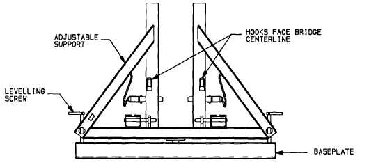
Position and hold a roller beam adjustable support on each front roller beam baseplate.
(a)
Ensure that hooks on supports face centerline.
(b)
Seat levelling screws in holes of baseplates.
CAUTION
Damage to equipment will occur If the levelling screws are not adjusted to allow 1/4 in (6 mm) gap.
(c)
Turn the adjustable support levelling screws into the baseplate sockets so that adjustable support is
vertical. Allow 1/4 in (6 mm) space between screw and socket so that the support may rock back and
forth on the pivot (front to rear).
4-5


