ARMY TM 5-5420-212-10-1
MARINE CORPS TM 08676A-10/1-1
5-4.
DISASSEMBLY - SINGLE STORY -12 BAY
This paragraph provides the steps to disassemble the Single Story 12 Bay MGB on the original near bank. The
bridge can be disassembled on the original far bank or near bank. If the bridge is to be disassembled on the far bank, the
erection equipment and launching nose parts must change sides.
a.
Preparation for Disassembly
(1)
If pumps, hoses and water are available, the bridge and erection components should be washed before
loading them on pallets.
(2)
If washing is not possible, the parts are loaded directly onto the proper pallet.
b.
Disassembly
(1)
Remove bridge classification signs.
(2)
Remove bridge guide markers (reverse of para. 4-26).
(3)
Remove all curbs (reverse of para. 4-26).
(4)
Remove ramp units on far bank, removing center ramp first (reverse of para. 4-24)
(5)
Remove all deck units (reverse of para. 4-25), leaving a deck unit in the third recess of bay 3 and
another at the rear of bay7. Start on far bank end of bridge.
(6)
Remove ramp units on near bank, removing center ramp first.
WARNING
The near bank end of bridge Is always raised and placed on a roller beam before the far bank end
of bridge is raised.
(7)
Jack up near bank end of bridge high enough to slide assembled roller beam under. Place packing
under girders as close to edge of gap as possible while bridge is being raised.
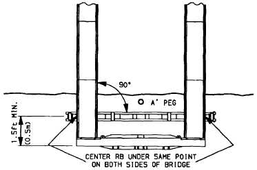
(8)
Lower bridge onto packing, remove jacks, and slide roller beam under end of bridge at least 1.5 ft (0.5
m) from end of bridge. If minimum bearing has been used, position roller beam under center hole of
bankseat beam.
(a)
Ensure that roller beam rollers are locked.
5-27