ARMY TM 5-5420-212-10-1
MARINE CORPS TM 08676A-10/1-1
(33) Remove launching nose heavy section 1 N1 as it passes landing roller.
(34) Remove push bar and push bar cross girder.
(35) Add bays 10,11 and 12. Insert a headless pin between bays 10 and 11 in case the bridge is to be
disassembled on the far bank.
(36) Connect rear bankseat beam. It may be necessary to level and square bridge girders so that the
bankseat beam will connect (para. 4-9a.).
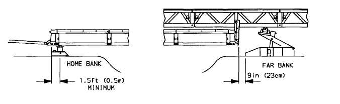
(37) Unlock rollers. Using vehicle launch bridge until the front bankseat beam is within 9 in (23 cm) of
landing roller pedestal. Stop launch, lock rollers. The near bank end of bridge should be 1.5 ft (0.5 m)
or greater from the roller beam rollers, or if minimum bearing is being used, rollers will be under center
hole in bankseat beam.
WARNING
Carelessness and improper operation of the hydraulic jack in the landing roller pedestal may
result In serious injury to personnel.
(38) Lower far bank end of bridge by operating jack in landing roller pedestal.
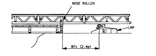
(39) Reposition landing roller pedestal so that center of roller is 8 ft (2.4 m) from nose roller on bankseat
beam, then raise landing roller pedestal until roller touches bottom of launching nose.
(40) Remove launching nose heavy sections [para. 4-13a. steps (4) to (9)].
(41) Remove launching nose cross girder and posts; use 6 personnel [para. 4-11a. step (7)].
(42) Disconnect vehicle from bridge.
5-25