ARMY TM 5-5420-212-10-1
MARINE CORPS TM 08676A-10/1-1
1-9.
LOCATION AND DESCRIPTION OF MAJOR COMPONENTS
a.
Bridge Components. Each bridge component is Illustrated and its function explained.
(1)
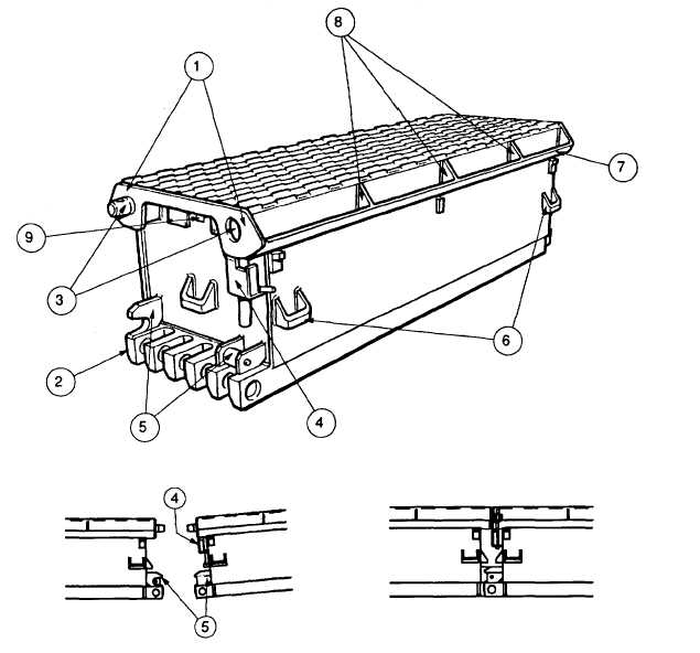
Top Panel (TP)
Top panels form the main girders of the bridge. Top panels, bankseat beams and junction panels have similar
dowels, sockets, shoot bolts, compression faces, guide slots, resilient mounts, and pin jaws.
To connect one top panel to another top panel, bankseat beam or junction panel, the dowel and socket is lined up
until the compression faces butt together, then the shoot boll handle is lifted and turned to lock the shoot bolt. The rear of
the panel is then lowered to allow the resilient mounts to mate in the guide slot and line up the pin jaws. A panel pin is
pushed through the pin jaws by hand, and a retainer clip is inserted through the end of the panel pin. The top panel is a
non-directional panel and is carried by four personnel.
(1)
COMPRESSION FACE. Takes compression load when bridge is completed. Used to line up panels, to close
shoot bolts.
TOP PANEL
JOINING PANELS
1-15


