ARMY TM 5-5420-212-10-1
MARINE CORPS TM 08676A-10/1-1
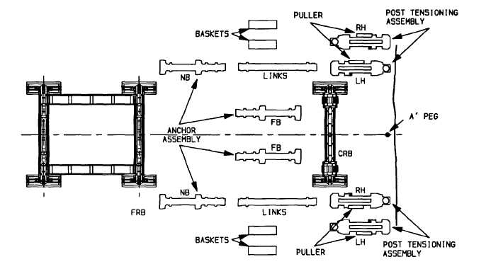
(2)
Check post tensioning assemblies (para. 4-16b.).
(a)
Ensure right hand (RH) and left hand (LH) are positioned as shown.
(b)
Ensure they are complete and ready for operation.
(c)
Check pullers and tackle blocks and make sure they are fitted on the correct outer position for the
side of bridge the post tensioners are to be placed.
(3)
Check anchor assemblies.
(a)
Ensure assemblies are complete.
(b)
Ensure far bank assemblies are positioned with junction block farthest from capsill roller beam and
near bank assemblies positioned with junction block facing edge of gap.
(4)
Stack links one on top of another.
(5)
Assemble end of bridge, launching nose up to 6N1 and bays 1 to 5 in the same way as when
constructing a 2E + 12 bay double story bridge [para. 6-1b. steps (1) thru (10) but DO NOT add a deck
unit in bay 1].
NOTE
A landing roller pedestal Mk 2, 20 ton hydraulic jack (fully extended), jack handle and four pieces
of packing (3 In x 8 In x 36 In) are placed on the launching nose.
NOTE
The bottom panel pins at 5p0 and 6p0 must be watched to ensure they remain fully seated In pin
jaws. Also bottom panel pins in last bay of bridge must be fully seated. If any of these pins are
allowed to creep out during assembly, difficulty In attaching the post tensioning assemblies will
arise.
7-15