ARMY TM 5-5420-212-10-1
MARINE CORPS TM 08676A-10/1-1
(30) Fit light tackle to second reinforcing link and bridge.
WARNING
Launch is done with a vehicle and push bar. Once vehicle is connected to bridge it must not be
disconnected until far bank end of bridge has been jacked down. Check push bar is correct way
up. During launching, reinforcing links, light tackle and anti-flutter tackle will be added.
(31) Unlock rollers and launch bridge to 10p0 (over CRB). Do not lock rollers, the vehicle is used to hold
bridge.
(32) Raise bridge, under control, until nose touches far bank.
CAUTION
A landing zone number two higher than the given LZ Is permitted. Never use an LZ number lower
than that given for the bridge being constructed.
(33) Set up landing roller pedestal Mk2 against the A peg on far bank (para. 4-15a.) and check that LZ2 or
higher is over center of LRP rollers (para. 4-4).
(34) Launch bridge to 15p0 (over CRB). During the launch:
(a)
Add long links with light tackle on each long link.
(b)
Add anti flutter tackle at 11pl.
(c)
Remove launching nose sections observing the 5 ft (1.5 m) minimum overhang (para. 4-13).
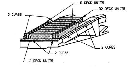
(35) Add thirty seven deck units and six curbs as counterweight, making a total counterweight of forty deck
units and six curbs. Position a flat bed vehicle close to the end of bridge and use personnel standing on
vehicle to transfer the counterweight from ground level up to personnel on the end of bridge.
(36) Launch bridge to 19p5 (over CRB), adding light tackle, long links and removing launching nose sections
as described in step (34).
7-19


