ARMY TM 5-5420-212-10-1
MARINE CORPS TM 08676A-10/1-1
Section III. COUNTERWEIGHTS - LINK REINFORCED BRIDGES
It is necessary to use counterweights during assembly/de-launch of 2E + 19 thru 2E + 22 bay link reinforced
bridges on normal sites. The following paragraphs describe the counterweights, but do not describe when they are added
or removed. This depends on the size of bridge and type of site.
NOTE
It is important to always refer to the build and boom or de-launch table for the bridge being built or
delaunched, to determine when the counterwelghts are added or removed.
7-4.
2E + 19 BAY - NORMAL SITE
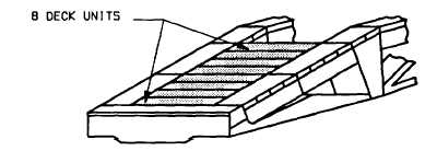
On 2E + 19 bay link reinforced bridges, eight deck units are placed in their final position on the end of bridge as a
counterweight.
7-5.
2E +20 BAY - NORMAL SITE
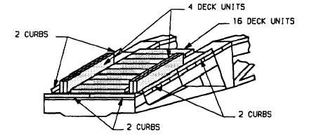
On 2E + 20 bay link reinforced bridges, twenty deck units and six curbs are placed on the rear end of bridge as
counterweight.
Eight deck units are placed in their final position on the end of bridge. Two curbs are placed on the bankseat
beam and four curbs on the top panels to retain the counterweight. The additional twelve deck units are placed on
decking, eight laid flat and four on edge leaning toward deck units as shown.
7-6.
2E + 21 BAY - NORMAL SITE
On 2E + 21 bay link reinforced bridges, thirty deck units and six curbs are placed on the rear end of bridge as
counterweight. The counterweight is added in two stages.
7-38