ARMY TM 5-5420-212-10-1
MARINE CORPS TM 08676A-10/1-1
(4)
Remove long link.
(5)
Remove fork end anchors of anchor assembly short link from bottom panel at 2p0.
CAUTION
Place packing (3 In x 8 In x 84 In) on ground so that the anchor assembly runs on the packing
during booming.
(6)
Boom to 10p0 over rear roller beam. Lock rollers and disconnect push bar.
(7)
Remove fork end anchors of anchor assembly long link from bottom panel at 1p0.
(8)
Remove deck unit from bay 17 and remove top panel 18, bays 17,16, 15,14 and bottom panel 13.
(9)
Boom the bridge as described below to 4p3 over rear roller beam. During this boom the end of bridge
will leave CRB.
(a)
Boom bridge until bankseat beam is 1 ft (0.3 m) gap side of capsill roller beam. Stop boom but do
not lock rollers, vehicle is holding bridge.
(b)
Raise FRB into contact with the bridge and at the same time lower the CRB so that the weight of
the bridge is gradually transferred from the CRB to the FRB. Careful transfer of weight from CRB to
FRB should achieve the correct working height at the end of bridge.
(c)
Continue boom to 4p3 (over RRB). Lock rollers and disconnect push bar.
(d)
If proper working height was not achieved at (b), adjust FRB and RRB to accommodate easy
disassembly. Level roller beams.
(10) Disassemble and remove capsill roller beam from site.
(11) Remove top panel 13, deck unit from bay 11, bay 12 and bottom panel 11.
(12) Boom to 3p0 over rear roller beam. Lock rollers and disconnect push bar.
(13) Remove top panel 11, bay 10 and bottom panel 9.
(14) Boom to 1p7 over rear roller beam. Lock rollers and disconnect push bar.
(15) Remove deck unit from bay 7 and remove top panel 9, bay 8 and bottom panel 7.
(16) Remove double story nose 3N2, 2N2 and 1N2.
(17) Remove top panel 7, bays 6, 5 and bottom panel 4.
(18) Remove remainder of launching nose.
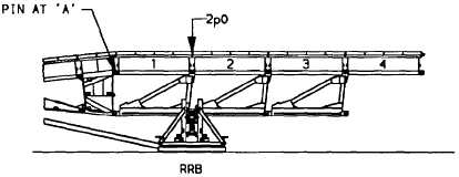
(19) Boom to 2p0 and remove pin at A.
7-35


