
TM 5-5420-226-20-2
MANIFOLD HEATER FUEL RETURN TUBE ASSEMBLY REPLACEMENT (LEFT AND RIGHT
BANK) (Sheet 4 of 7)
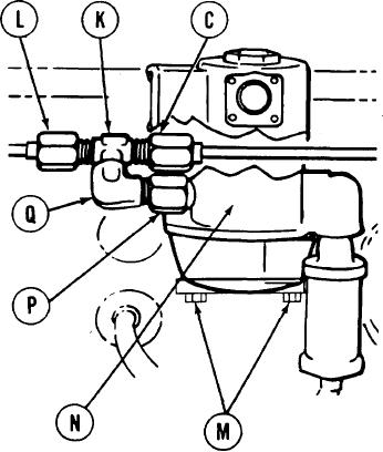
8.
Using 9/16 inch wrench, remove line nut
of tube assembly (C) from tee (K).
Using 9/16 inch wrench, remove line nut
9.
of tube assembly (L) from tee (K).
10.
Using 5/16 inch open end wrench, remove
two screws (M) and pull solenoid valve
(N) forward approximately 1 inch.
11.
Using 1/2 inch open end wrench on
coupling (P), remove coupling (P)
with elbow (Q) and tee (K) attached.
Using 9/16 inch wrench on elbow (Q) and
12.
adjustable wrench on tee (K), remove tee
(K) from elbow (Q).
13.
Using 9/16 inch wrench on elbow (Q) and
1/2 inch wrench on coupling (P), remove
elbow (Q) from coupling (P).
Push engine cooling fan shroud aside to
14.
allow clearance for removal of tube
assembly (C). Other person, using both
hands, carefully remove tube assembly
(C) from engine.
CLEANING AND INSPECTION:
1. Using clean rags and so solvent, clean fittings thoroughly.
2. Inspect fittings for nicks, cracks, thread damage, or wear. Replace if required.
3. Inspect internal threads of manifold heater and solenoid adapter for damage.
Go on to Sheet 5
TA107886