
TM 5-5420-226-20-3
MASTER CONTROL PANEL REPAIR (Sheet 33 of 73)
Circuit Breaker Replacement (Sheet 1 of 7)
PROCEDURE INDEX
PAGE
PROCEDURE
Removal (A, B, C,and E)
Installation (A,B,C, and E)
Removal (D)
Installation (D)
Removal (F)
Installation (F)
Removal (G)
Installation (G)
4 in. flat-tip screwdriver
3/8 in. socket with 1/2 in. drive
TOOLS:
Ratchet with 1/2 in. drive
Cross-tip screwdriver
11/32 in. wrench
SUPPLIES:
Silicone compound (Item 32, Appendix D)
PRELIMINARY PROCEDURE: Remove panel from vehicle (page 10-34).
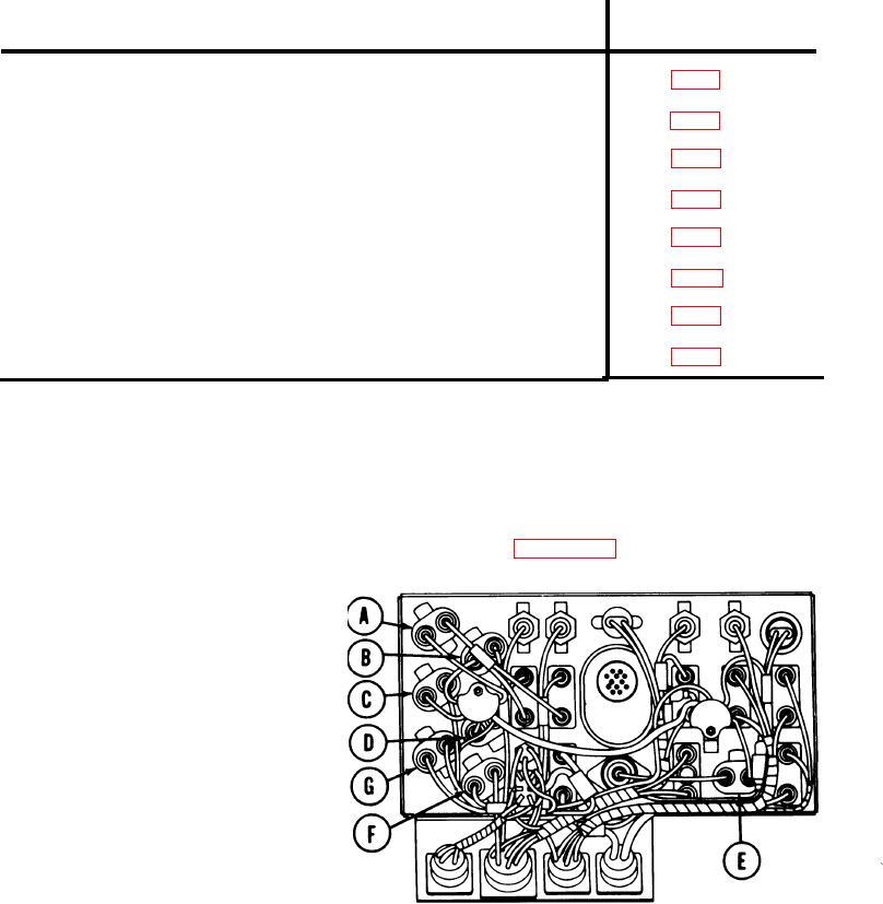
NOTE
There are seven circuit breakers located
Five
in the master control panel.
circuit breakers (gas particulate (A),
I R (night vision), power (B), fuel shut-
off (C), fuel pump (D) and bilge pump
and utility outlet (E)) are. replaced by
removing mounting screws from the
Two circuit
front of the panel.
breakers (gage (F) and manifold pre-
heat (G) are replaced by mounting
screws from the rear of the panel.
TA168721
Go on to Sheet 2