• Google+Share on Google+
    • FacebookShare on Facebook
    • LinkedInShare on LinkedIn
    • TwitterShare on Twitter
    • DiggShare on Digg
    • StumbleUponShare on StumbleUpon
    • Home
    • Download PDF
    • Order CD-ROM
    • Order in Print
    SHIFT LINKAGE ADJUSTMENT - Continued
    SHIFT LINKAGE ADJUSTMENT - Continued

    M48A5 Tank Chassis, Transporting: For Bridge, Armored-Vehicle-Launched; Scissoring Type, Class 60 -3 Page Navigation
      517    518    519    520    521  522  523    524    525    526    527  
    img
    TM 5-5420-226-20-3
    SHIFT LINKAGE ADJUSTMENT (Sheet 3 of 28)
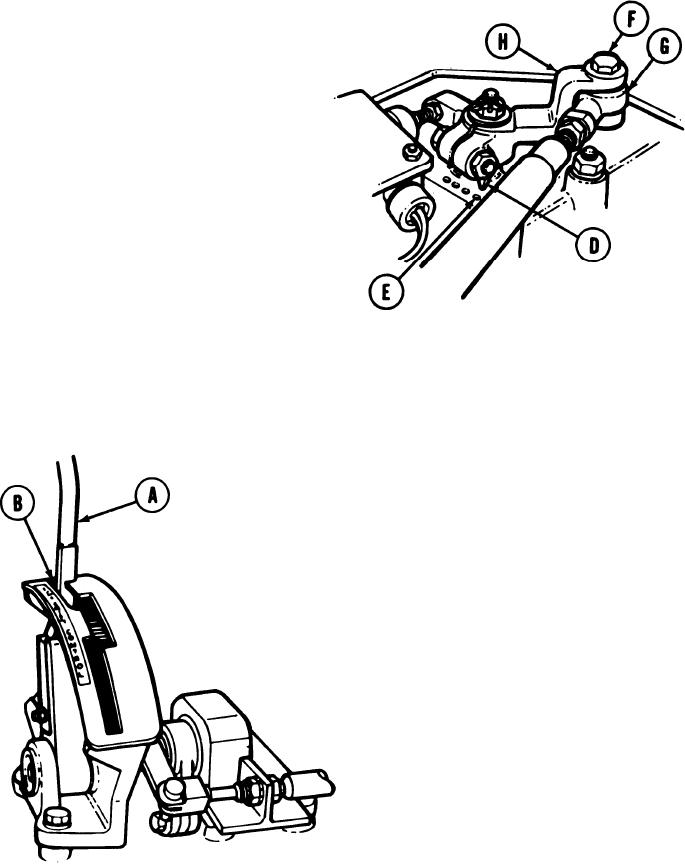
    At top of transmission, check position
    3.
    of shifting position indicator (D). If
    shifting position indicator (D) is
    pointing to most forward dot (E), notify
    support maintenance.
    NOTE
    Linkage is in adjustment, but transmission
    malfuntion is indicated.
    If shifting position indicator (D) is not
    pointing to most forward dot (E), go to step
    126.
    TOP OF TRANSMISSION
    At top of transmission, using 9/16 inch wrench, remove screw (F) and remove shifting
    4.
    rod bearing end (G) from clevis (H).
    At driver's station, move transmission
    5.
    shift lever (A) to P position (B).
    DRIVER'S STATION
    TA169056
    Go on to Sheet 4
    11-55


    Privacy Statement
    Press Release
    Contact

    © Copyright Integrated Publishing, Inc.. All Rights Reserved.