
TM 5-5420-226-20-3
SHIFT LINKAGE ADJUSTMENT (Sheet 5 of 28)
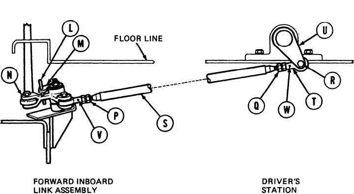
Using 9/16 inch wrench, loosen jamnuts
10.
(P) and (Q).
11.
Using 9/16 inch wrench, remove screw (R).
Manually move shifting rod (S) and insert
12.
locating pin (L) into alinement holes in
bracket (M) and link (N).
13.
Using 9/16 inch wrench, adjust shifting rod bearing end (T) by turning clockwise or
counterclockwise until screw (R) will slip freely through link (U) and shifting rod bearing
end (T).
Using small diameter wire, check to see if shifting rod (S) is past holes (V) and (W). If
14.
shifting rod (S) is past holes (V) and (W), do steps 15 thru 18. If shifting rod (S) is not past
hole (W), do steps 19 thru 28. If shifting rod (S) is not past hole (V) go on to step 29.
TA169058
Go on to Sheet 6
11-57