
TM 5-5420-227-24
VALVE BANK ASSEMBLY CONTROLS REPLACEMENT (Sheet 2 of 2)
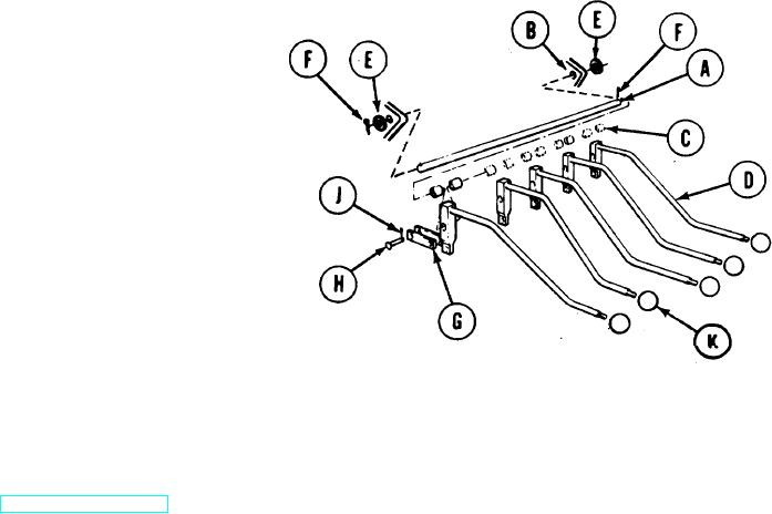
INSTALLATION:
1.
Manually start pin(A) through
valve bank (B).
2.
While tapping pin (A), install
ten spacers (C) and five
control levers (D) as shown.
3.
Using pliers, install two washers
(E) and new cotter pins (F).
Place ten links (G) in position.
4.
5.
Manually install ten
straight pins (H).
6.
Using pliers, install ten new cotter
pins (J).
7.
Manually screw five knobs (K) onto five control levers (D).
8.
Operate each control lever (D) to
insure proper operation.
End of Task
TA170344
3-118