
TM 5-5420-227-24
HOLD DOWN CYLINDER HOSE ASSEMBLIES (CU1, CU2, CV1 THRU CV4) AND HYDRAULICS
REPLACEMENT (Sheet 1 of 5)
PROCEDURE INDEX
PROCEDURE
PAGE
Removal
Installation
TOOLS: 7/8 in. open end wrench
13/16 in. combination box and open end wrench
12 in. adjustable wrench
1-1/4 in. open end wrench
Vise
SUPPLIES:
Drip pans
Pencil
Rags (Item 12, Appendix D)
Masking tape (Item 18, Appendix D)
Pipe tape (Item 19, Appendix D)
Caps and plugs (assorted sizes)
REFERENCES:
PRELIMINARY PROCEDURES:
Relieve hydraulic pressure (page 3-65)
Remove front quadrant (page 3-39) CU1 and CU2 hose
assemblies only
Remove powerplant (TM 5-5420-226-20) CV1 and CV2 hose
assemblies only
Remove hold down cylinder armor (page 3-247) CV3 and
QUADRANTS REMOVED
CV4 hose assemblies only
FOR CLARITY
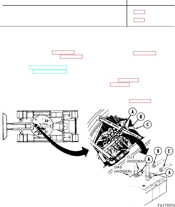
REMOVAL:
NOTE
Use rags and drip pans to catch excess
hydraulic fluid. Use tape to tag lines for
installation. Cap all lines and fittings as
disconnected.
1.
Holding two adapters (A) with 1-1/4 inch
wrench, use 7/8 inch wrench to disconnect
hose assemblies "CU1" (B) and "CU2" (C).
Go on to Sheet 2
3-167