
TM 5-5420-227-24
HYDRAULIC FLUID FILTER ASSEMBLY REPLACEMENT (Sheet 1 of 3)
TOOLS: 7/16 in. open end wrench
1/4 in. socket head screw key
1-1/2 in. open end wrench
18 in. pipe wrench
15 in. adjustable wrench
Vise
SUPPLIES:
Drip pan
Rags (Item 12, Appendix D)
Lockwasher
Pipe tape (It em 19, Appendix D)
REFERENCE:
PRELIMINARY PROCEDURE:
Drain hydraulic reservoir (page 3-68)
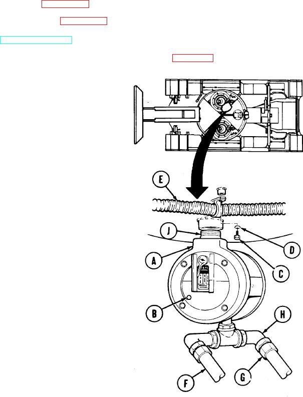
REMOVAL:
NOTE
Use drip pan to catch hydraulic fluid
trapped in filter assembly (A).
1.
Using 1/4 inch screw key, remove pipe plug
(B).
2.
After hydraulic fluid has stopped draining
from filter assembly (A), use 1/4 inch screw
key to install plug (B) in filter assembly (A).
3.
Using 7/16 inch wrench, remove screw (C)
and lockwasher (D). Throw lockwasher (D)
away.
4.
Lower hose (E) to allow access to filter
assembly (A).
NOTE
Use rags and drip pan to catch hydrau-
lic fluid trapped in hoses (F and G).
5.
Using 1-1/2 inch wrench, remove hose
assembly "CY" (F).
6.
Using adjustable wrench, remove collar and
hose assembly "CZ" (G).
7.
Using adjustable wrench, remove elbow (H).
8.
Using pipe wrench, remove nipple (J) with
filter assembly (A) attached.
Place filter assembly (A) in vise.
9.
Go on to Sheet 2
TA170426
3-202