• Google+Share on Google+
    • FacebookShare on Facebook
    • LinkedInShare on LinkedIn
    • TwitterShare on Twitter
    • DiggShare on Digg
    • StumbleUponShare on StumbleUpon
    • Home
    • Download PDF
    • Order CD-ROM
    • Order in Print
    PUMP-CLUTCH COVER PLATE REPLACEMENT (Sheet 1 of 1)
    Section Il. VALVES AND ASSOCIATED HYDRAULICS

    Launcher Hydraulics System M48A5/M60A1 Tank Chassis, Transporting: For Bridge, Armored-Vehicle-Launched; Scissoring Type, Class 60 Page Navigation
      223    224    225    226    227  228  229    230    231    232    233  
    img
    . . .
    TM 5-5420-228-24
    HYDRAULIC CLUTCH ADJUSTMENT (Sheet 1 of 1)
    SUPPLIES:
    Lockwire
    REFERENCE: TM 5-5420-202-10
    PRELIMINARY
    PROCEDURE:
    Remove pump-clutch cover plate (page 3-65).
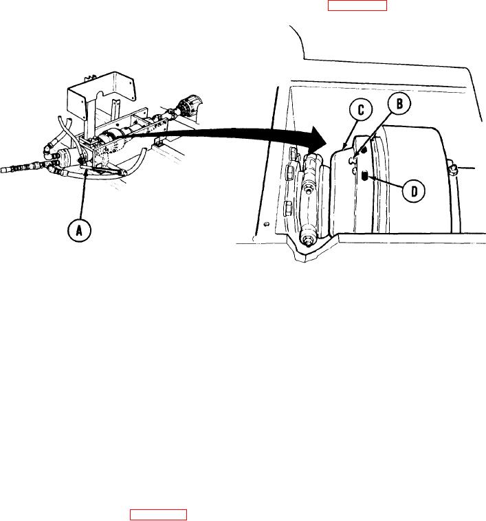
    ADJUSTMENT:
    Push clutch control lever (A) downward to disengage.
    1.
    2. Turn clutch manually until pin (B) can be reached.
    Pull pin (B) out and lock by inserting lockwire through hole in pin (B).
    3.
    Turn cover (C) clockwise one or two adjusting holes (D).
    4.
    5. Pull clutch control lever (A) up to engage.
    6. Repeat steps 4 and 5 until clutch control lever (A) requires definite force to engage clutch.
    7. Remove lockwire from pin (B) and push pin in.
    8. Install pump-clutch cover (page 3-65)
    9. Operate pump-clutch to insure proper operation (TM 5-5420-202-10).
    TA251466
    End of Task
    3-66


    Privacy Statement
    Press Release
    Contact

    © Copyright Integrated Publishing, Inc.. All Rights Reserved.