
TM 5-5420-228-24
SEQUENCE RELIEF VALVE (RV5) ADJUSTMENT (Sheet 1 of 1)
TOOLS: 3/16 in. socket head screw key
1/4 in. socket head screw key
9/16 in. open end wrench
Gage, pressure (item 3, sec III, app B)
SPECIAL TOOL:
PERSONNEL:
Two
REFERENCE:
TM 5-5420-202-10
Relieve hydraulic pressusre (page 3-71)
PRELIMINARY
PROCEDURE:
NOTE
If STE/lCE is available, go to STE/lCE Test
51 (page 2-47).
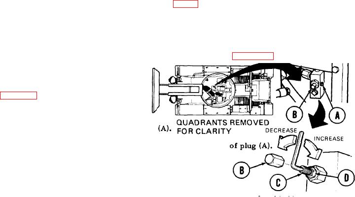
ADJUSTMENT:
1.
Using 1/4 inch screw key, remove plug
Manually install pressure gage in opening left by removal
2.
Engage hydraulic pump (TM 5-5420-202-10).
3.
Set engine speed at 1800 rpm.
4.
Slowly push up tongue cylinder control lever all the way to extend and hold in that position.
5.
Have second technician observe pressure gage reading.
6.
Return tongue cylinder control lever to neutral position.
7.
Remove adjusting screw cap (B) using wrench.
8.
NOTE
Correct pressure is 700 50 psi (4826 340 kPa).
To adjust relief valve pressure, hold adjusting screw (C) with 3/16 inch screw key and
9.
use wrench to loosen jamnut (D). Using 3/16 inch screw key, turn adjusting screw (C)
clockwise to increase pressure or counterclockwise to decrease pressure.
Repeat steps 3 through 9 until pressure gage shows reading of 700 50 psi (4826 --
340
10.
kPa).
Holding adjusting screw (C) with 3/16 inch screw key, use wrench to tighten jamnut
11.
(D).
Install adjusting screw cap (B) using wrench.
12.
Remove pressure gage.
13.
14.
Using 1/4 inch screw key. install plug (A) and tighten.
TA251484
End of Task