
TM 5-5420-228-24
MASTER RELIEF VALVE (RV1) AND CHECK VALVE (CV1) REPLACEMENT (Sheet 1 of 3)
1-7/16
in. open end wrench
TOOLS:
12 in.
adjustable wrench
15 in.
adjustable wrench
10 in.
pipe wrench
Drip pans (suitable containers)
SUPPLIES:
Rags (Item 12, Appendix D)
Pipe tape (Item 19, Appendix D)
Masking tape (Item 18, Appendix D)
Pencil (Item 22, Appendix D)
Protective caps and plugs
Nipple
TM 11-5820-498-12
LO 5-5420-202-12
REFERENCES:
TM 5-5420-202-10
Relieve hydraulic pressure (page 3-71)
PRELIMINARY PROCEDURES:
Remove radio from mount (TM 11-5820-498-12)
Drain hydraulic reservoir (page 3-74)
Cap or plug all lines and fittings as they are dis-
connected. Use rags and drip pans to catch ex-
cess hydraulic fluid. Use tape to tag lines for
installation.
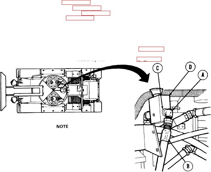
REMOVAL:
1.
Holding elbow (A) with 12 inch adjustable
wrench, use 1-7/16 inch wrench to dis-
connect hose assembly "BA" (B).
2.
Using 12 inch adjustable wrench, remove elbow (A) and collar "BA" (C) from master
relief valve "RV1" (D).
Go on to Sheet 2
TA251488