
TM 5-5420-228-24
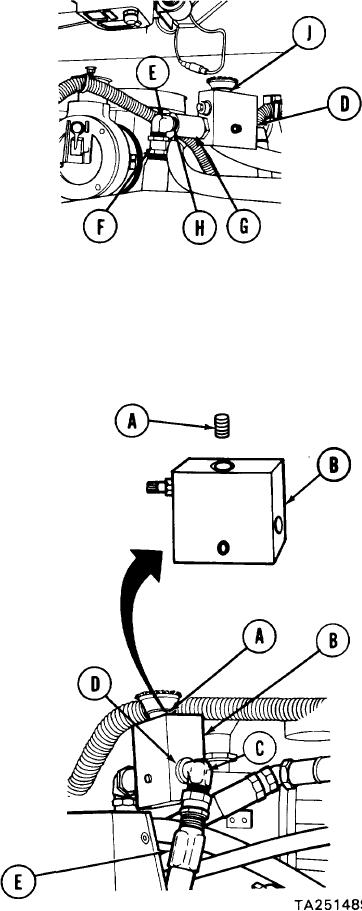
MASTER RELIEF VALVE (RV1) AND CHECK VALVE (CV1) REPLACEMENT (Sheet 2 of 3)
Holding elbow (E) with 12 inch adjustable
3.
wrench, use 1-7/ 16 inch wrench to dis-
connect hose assembly "CY" (F).
Holding check valve "CVI" (G) with 15 inch
4.
adjust able wrench, use 12 inch adjustable wrench
to remove elbow (E) and collar "CY" (H).
Using 15 inch adjustable wrench, remove
5.
check valve "CV1" (G).
Using 15 inch adjustable wrench, remove master relief valve "RVI" (D).
6.
If nipple (J) was removed with master relief valve "RV1" (D), use pipe wrench to remove
7.
nipple (J) and throw it away.
INSTALLATION:
NOTE
Remove all caps and plugs as necessary during installation.
Before installing, use pipe tape on all male threads. Start
tape on second thread so tape will not enter hydraulic
system.
If nipple (A) was removed, manually
1.
install nipple in top port of relief
valve "RV1" (B).
NOTE
Be sure to install master relief valve "RV1" (B) as shown.
Using 15 inch adjustable wrench, install
2.
master relief valve "RV1" (B) and nipple
(A) in base of reservoir.
Using 12 inch adjustable wrench, install
3.
elbow (C) and collar "BA" (D).
Holding elbow (C) with 12 inch adjustable
4.
wrench, use 1-7/16 inch wrench to install
hose assembly "BA" (E).
Go on to Sheet 3