
TM-5-5420-279-10
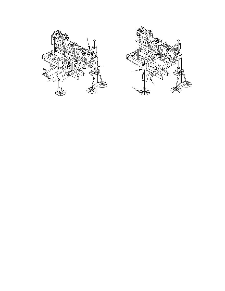
UPPER
A-FRAME
A-FRAME
FOLDING
RAMS
A-FRAME
ACTUATOR
A-FRAME
A-FRAME
STABILIZER
SUPPORTS
LOWER
A-FRAME
A-FRAME IN LOW POSITION
A-FRAME IN RAISED POSITION
686A575
Figure 2. 5 A-Frame
Lower A-Frame Transverse Beam
The lower A-frame transverse beam spans the rear of the vehicle and attaches to the rear of the
slide frame by a hinged arrangement, and to the A-frame legs at their hinge points. The beam
provides mounting for the A-frame to fold and rotate. A spirit level installed on the beam
accurately positions the horizontal axis of the A-frame by adjustment of the stabilizer legs.
A-Frame Legs
2.1.9.1
The A-frame legs consist of the leg itself and an internal sliding stabilizer leg to which
is attached a circular baseplate. The stabilizer leg is extended or retracted by the
stabilizer cylinder to vary the height of the A-frame. The control valve for manual
operation of the A-frame stabilizer leg is mounted on the outer face of the lower
center beam.
Hydraulic Cylinders
2.1.10.1
The A-frame rotate hydraulic cylinders rotate the A-frame assembly from its stowed to
its working position.
2.1.10.2
The A-frame folding hydraulic cylinders fold the A-frame legs from the stowed to the
working position.
2.1.10.3
The A-frame stabilizer leg cylinders are extended and or retracted to allow the
launching equipment to be leveled ready for bridge building.
2.1.10.4
The A-frame raise hydraulic cylinders elevate the upper A-frame transverse beam
ready for bridge deployment.
2.1.10.5
Two articulator cylinders are connected to the launch frame and the slide frame cross
member. They are used to articulate the launch beam to accommodate varying bank
heights. To allow bridge build the articulator cylinders are detached from the slide
frame cross member and stowed. To facilitate stowing, stow cylinders are used to
rotate the articulator cylinders clear of the bridge surface during building.
