TM-5-5420-279-10
2.1.18.3
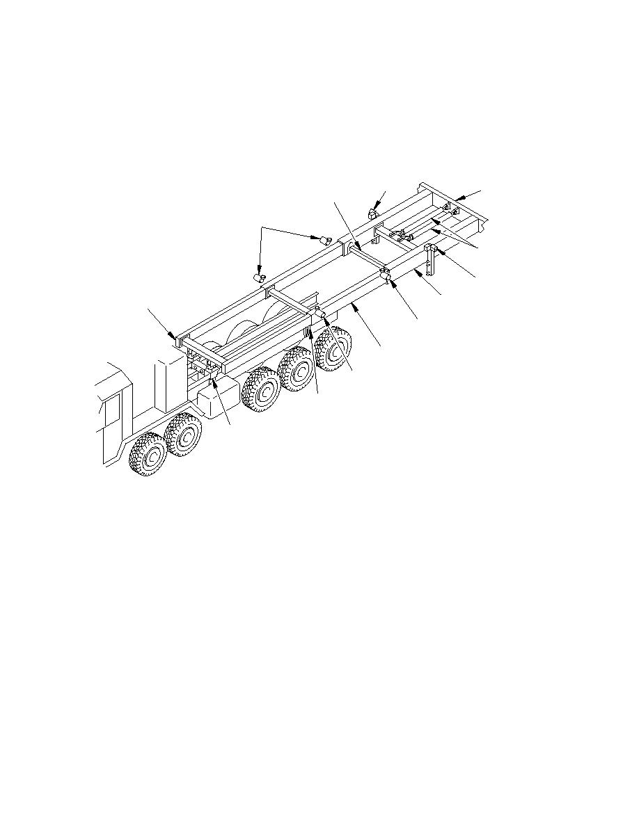
The left and right hand sections of the slide frame are connected by two cross
members. Twist-lock blocks mounted on a bracket at either side of Section 3 retain
the slide frame in the transportation position, until released for deployment. Release
of the twist-lock fasteners allows the deployment of the slide frame by driving the
launch vehicle forwards.
TILT
'A' FRAME
ROLLER
ARTICULATOR
LOWER
CROSS MEMBER
TRANSVERSE
BEAM
REMOVEABLE
ROLLERS
'A' FRAME
ROTATE RAMS
TILT
INNER
ROLLER
SLIDE FRAME
OUTER SLIDE FRAME
SECTION 1
SECTION 3
REMOVEABLE
ROLLERS
CENTER SLIDE FRAME
SECTION 2
REMOVEABLE
ROLLERS
TWIST LOCK
FASTENER
RELAX
MECHANISM
WF/0029a
Figure 2. 10 Slide Frame
Relax Mechanism
2.1.19.1
The relax mechanism attaches Section 1 of the slide frame to the vehicle chassis.
The mechanism is unlocked by manual operation of shootbolts, the relax mechanism
allows a controlled sliding movement of -25 mm to +80 mm during bridge build.
2.1.19.2
Four hydraulic cylinders are used to re-set the relax mechanism to its neutral position
on completion of bridging operations. Movement of the cylinders re-aligns the holes to
permit re-installation of the shootbolts, locking the relax mechanism in its neutral
setting. Limit switches, operated by the shootbolts, prevent operation of the chest
pack controls until the relax mechanism is unlocked for operation.


