TM-5-5420-279-10
Hydraulic Controls
2.1.11.1
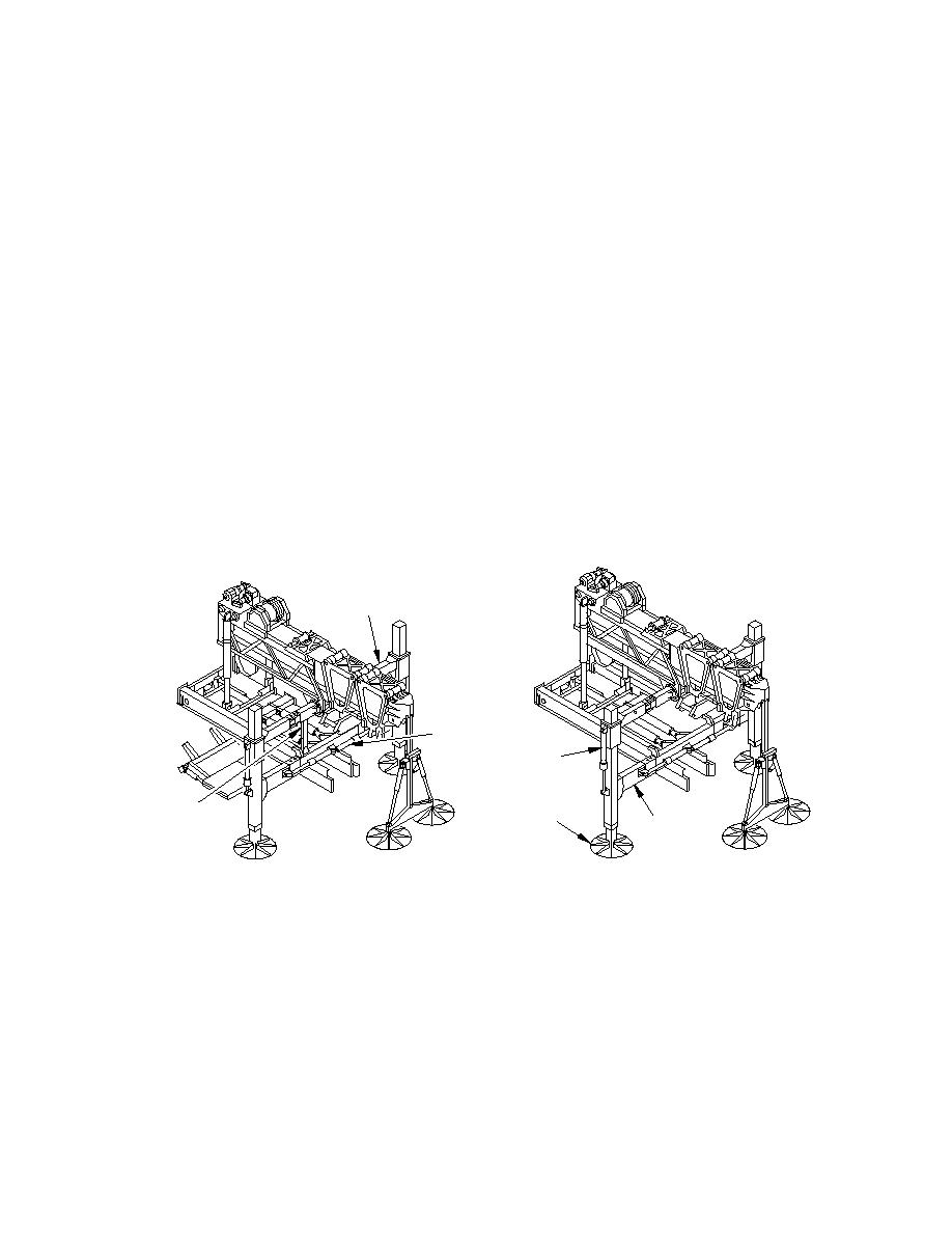
The hydraulic operation of the A-frame is controlled from two locations on the vehicle.
The A-frame fold and rotate functions are operated from the operators cabinet located
above the tool chest on the right hand side of the launch vehicle. Limit switches are
incorporated into the circuit to guard against incorrect sequencing of operations.
2.1.11.2
The A-frame stabilizer legs are operated by two manual levers mounted on the center
rear face of the lower A-frame transverse beam.
2.1.11.3
With the launcher deployed, hydraulic control is carried out via the chest pack.
Should electrical failure occur all cylinders and motors can be operated manually.
Launch Frame
2.1.12.1
The launch frame is a steel framework through which the launch beam passes during
launch beam deployment. It is attached at its forward end to the A-frame and at the
rear end to the slide frame via the articulator cylinders. Once beam deployment is
complete, the articulator cylinders are stowed. The forward launch beam is retained in
the launch frame after beam retrieval. Mounted on the launch frame are various roller
assemblies, hydraulic valves, winches and the launch beam drive unit.
2.1.12.2
At the back of the launch frame (by the articulating cylinders) is the launch beam stop.
This prevents over deployment of a launch beam if no following beam is attached.
UPPER
A-FRAME
A-FRAME
FOLDING
RAMS
A-FRAME
ACTUATOR
A-FRAME
A-FRAME
STABILIZER
SUPPORTS
LOWER
A-FRAME
A-FRAME IN LOW POSITION
A-FRAME IN RAISED POSITION
686A575
Figure 2. 6 A-Frame and Launch Frame
Roller Assemblies
2.1.13.1
At the bottom rear of the launch frame is a pinch roller, which ensures that the launch
beam maintains contact with the launch beam drive.
2.1.13.2
At the bottom front of the launch frame is a twin set of rollers, which support the
launch beam during deployment.


