
TM-5-5420-279-10
4.8.3.4
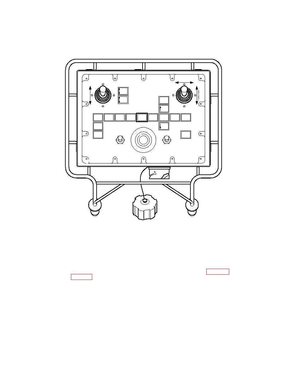
On the chest pack, move the joystick forwards to raise the A-frame and provide
clearance for the parallel modules to pass. Make sure the A-frame raise cylinders
extend and raise the A-frame to the upper sliding section.
FUNCTION
SELECT
TILT
ROLLER
CARRIAGE
STOW
EMPTY
HIGH
BANK
BEAM
FARBANK
A FRAME
MODE
BEAM
STOW
=LEVEK
L
TOP
BRIDGE
DRIVE
SEAT
RAISE
SELECT
ANGLE
ARTIC
BAN
WINCH
LIFT
LOW
EMERGENCY STOP
POWER
BANK
ROLLER
BRIGHT
OFF
FAULT
BRAKE
OFF
ON
DIM
OFF
ROLLER BRAKE
PUSH TO STOP - TWIST TO RESET
686A356e
A-frame Raise Caption
NOTE
The choice of locking pinholes to be used during bridge build in the A-frame stabilizer legs
is determined during the site reconnaissance stage.
4.8.3.5
Release the joystick when the A-frame has been raised above the pre-selected hole
and insert the locking pins and R clips. (For pinhole selection, see Chapter 1 Section
II Table 1. 5 Upper A-frame Setting).
NOTE
A choice of two hole locations to secure the A-frame in the upper position is available.
The holes located at the lower positions are used if the launch beam slopes from the
horizontal to a higher far bank. The holes located at the upper positions are used if the
launch beam slopes from the horizontal to a lower far bank.
4.8.3.6
On the chest pack, move the joystick rearwards to lower the A-frame until it sits on the
locking pins.
4-45
