TM-5-5420-279-10
5.4.2.22
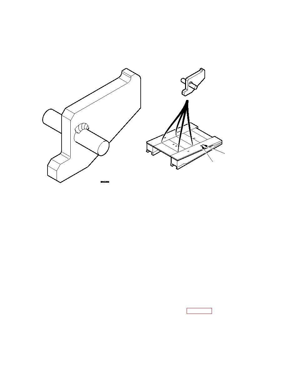
Recover the four approach ramp frame transport aids from the bridging basket.
5.4.2.23
Fit four approach ramp transport aids to the ramp module deck units between the 1st
and the 2nd deck unit from the jaw end and between 3rd & 4th deck unit from the
jaw end. The bracket is fitted with the white face up and facing outwards.
FRONT
POSITION 1
REAR
POSITION 2
A
Approach Ramp Transport Aid Locations
5.4.2.24
Reconfigure the module lifting beam to its widest setting and secure with shootbolts.
5.4.2.25
Operate the crane controls on the crane and position the bridge module lifter above
the stacked approach ramp transport frames positioned on flatrack V1.
5.4.2.26
Connect the bridge module lifter to the four connecting slings on the upper approach
ramp frame and connect two guide ropes.
5.4.2.27
Operate the crane controls on the crane to lift the approach ramps and position them
centrally on the ramp module on flatrack T1. Ensure the frame aligns with the white
marks on the ramp module and the transport aids located between the ramps deck
units.
5.4.2.28
Disconnect the bridge module lifter and tag lines from the approach ramp frame.
5.4.2.29
Disconnect the bridge module lifter and single leg sling from the crane and the tag
lines from the home bank ramp module.
5.4.2.30
Operate the controls on the crane and position the crane hook to lift the home bank
end beam.
5.4.2.31
Attach the end beam slings to the end beam as shown in Figure 5. 3.
5-18


