TM-5-5420-279-10
11.15.2.5
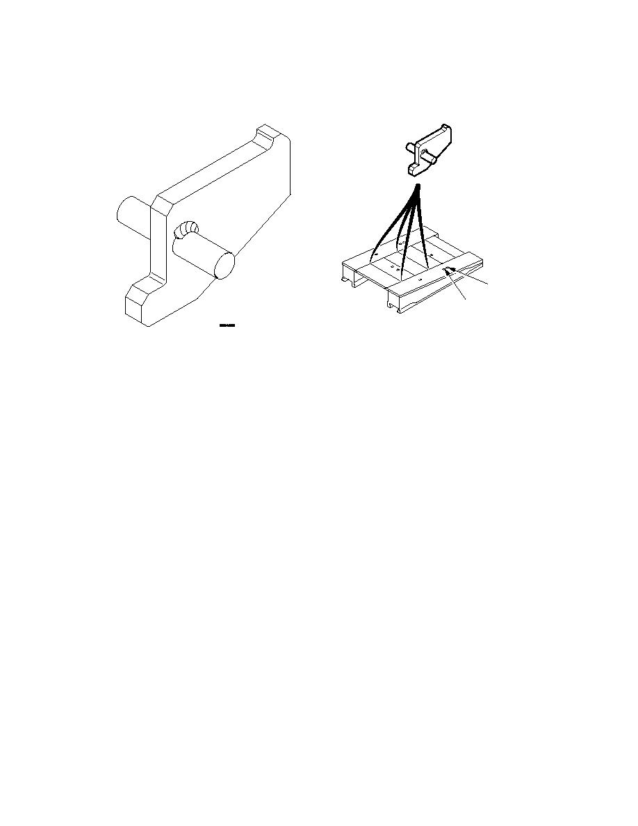
Fit the four approach ramp transport aids to the ramp module deck units between the
1st and the 2nd deck unit from the jaw end and between 3rd and 4th deck unit from
the jaw end.
FRONT
POSITION 1
REAR
POSITION 2
A
Figure 11. 106 Approach Ramp Frame Transport Aid
11.15.2.6
Position and centralize a loaded approach ramp frame onto the ramp module
ensuring that the location pads locate into the gaps in between the decks. Use the
centerline marked along the module deck as a guide. Place a further three approach
ramp frames on top ensuring that the location pads fit into the recesses in the posts
of the frame below.
11.15.2.7
On each side, hook the top end of a module access ladder around the approach
ramp frame posts allowing the other end to rest on the deck of the ramp module.
Secure each ladder by passing a BII strap through the rungs and around the frame
posts.
11.15.2.8
Fit four transportation straps around and over the top of the stack of approach ramp
frames and tighten using the ratchet. Two straps pass diagonally around the posts
on the upper frame.
11.15.2.9
Position two bridging timbers longitudinally on the edges of the module deck towards
the rear. Place two end beams with their lipped rails facing outwards on these
timbers. Bundle the 12 defile markers into two nesting layers of six. Secure
together using two 1.5-meter cam buckle straps and place the bundle on top of the
end beams.
11.15.2.10 Fit two flatrack BII straps around the end beams and tighten using the ratchets.
11-114


