TM 55-1945-205-24-2
0064 00 3
0064 00
2.
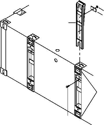
Disassemble the female guillotine connector assembly.
a.
Remove the guillotine connector bar (8).
{1} Remove bolt (9), nut (10) and friction plate (11).
{2} Pry up on the guillotine connector bar (8) using a crowbar.
b.
Remove guillotine connector bar (8) from guillotine lock housings (12).
INSPECT AND REPAIR/REPLACE COMBINATION BEACH/SEA END SECTION NON-POWERED
MODULE MALE AND FEMALE GUILLOTINE CONNECTORS
1.
Inspect male connector pins (5) for cracks, cuts or corrosion. If damaged, replace connector pins.
2.
Inspect deployment springs (7) for cracks, cuts or corrosion. If damaged, replace deployment springs.
3.
Inspect guillotine connector bars (1, 8) for cracks, cuts or corrosion. If damaged, repair or replace guillotine
connector bars (1, 8).
4.
Inspect guillotine connector male and female lock housings (6, 12) for cracks, cuts or corrosion. If damaged,
replace or replace guillotine connector lock housings (6, 12).
5.
Inspect guillotine connector assembly friction plates (4, 11) for cracks, cuts or corrosion. If damaged, replace
friction plates (4, 11).
9
10
8
12
11