TM 55-1945-205-24-4
0061 00 5/6 blank
0061 00
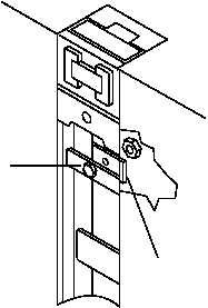
ASSEMBLY OF COMBINATION BEACH/SEA END SECTION NON-POWERED MODULE MALE AND
FEMALE GUILLOTINE CONNECTORS
1.
Assemble the female guillotine connector assembly.
a.
Install guillotine connector bar (8) into guillotine lock housing (12).
b.
Install bolt (9) through friction plate (11) and nut (10).
2.
Assemble the male guillotine connector assembly.
a.
Install guillotine connector bar (1) into guillotine lock housing (6).
b.
Install deployment spring (7) on male connector pin (5).
c.
Install male connector pin (5) into guillotine connector lock housing (6) by pushing down on the retainer
located on the underside of the male connector pin (5) to lock pin in place.
d.
Install bolt (2) through friction plate (4) and nut (3).
ADJUST COMBINATION BEACH/SEA END SECTION NON-POWERED MODULE MALE AND
FEMALE GUILLOTINE CONNECTORS
1.
Locate the friction plate (4) on the guillotine connector assembly.
CAUTION
Overtightening friction plate causes difficult operation of the guillotine. Failure to
comply may result in damage to equipment.
2.
Tighten bolt (2) using two standard wrenches.
3.
Remove block of wood.
4.
Perform operational check of guillotine connectors. (TM 55-1945-205-10-4)
END OF WORK PACKAGE
2
4