
TM 5-5420-228-24
CLUTCH ASSEMBLY REPLACEMENT AND REPAIR (Sheet 9 of 9)
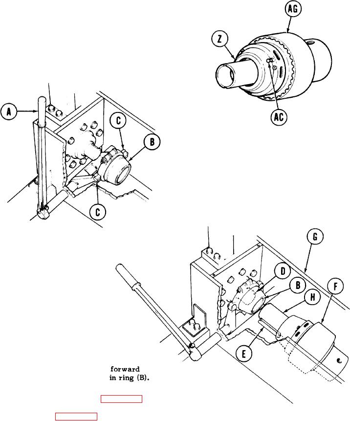
Place cover (Z) in clutch assembly (AG).
33.
Turn cover (Z) clockwise until installed
34.
on assembly (AG).
35.
Remove locating pin from pin (AC) to
lock cover (Z) in place.
INSTALLATION:
1.
Pull up lever (A).
2.
Place ring (B) and attached parts in yoke (C).
Push down lever (A) to be sure clutch is
3.
disengaged.
4.
Install two keys (D and E).
5.
Place clutch assembly (F) in
support (G).
Insert shaft" (H) in ring (B).
6.
P u s h clutch assembly (F)
7.
until shaft (H) is all the way
Install pump-clutch drive (page 4-25).
8.
Adjust clutch (page 3-66).
9.
TA251692
End of Task

