
TM 5-5420-202-20-2
POWERPLANT REPLACEMENT (Sheet 16 of 21)
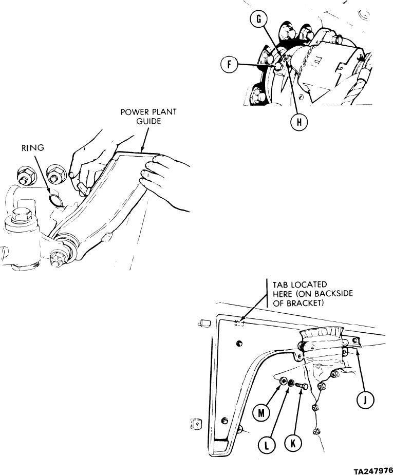
Install screw (F). Using 3/4 inch socket,
21.
tighten screw on each side. Torque screw
(F) to 10 to 20 lb-ft (14 to 27 NZm)
22.
String lockwire (G) through screw (F)
and opening in ring (H) on each side.
Raise guide lock latch.
23.
Push powerplant guide forward until
24.
lockring snaps into place.
Lay parking brake cable on top of trans-
25.
mission. Position angle bracket (J)
to rear side wall (by powerplant wide).
Hang tab of bracket onto tab on com-
partment side wall on each side.
Install three screws (K), lockwashers
26.
(L), and washers (M) to secure angle
bracket (J) to side wall (both sides).
27.
Using 9/1 6 inch socket
and 5 inch extension, tighten three screws
(K) (both sides) to secure bracket (J)
to side wall.
Go on to Sheet 17