
TM
5-5420-202-20-2
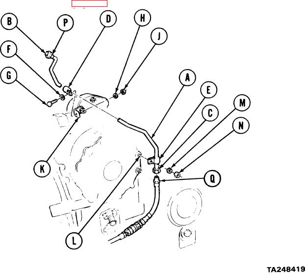
ENGINE FUEL RETURN TUBE ASSEMBLY REPLACEMENT (Sheet 3 of 3)
INSTALLATION:
Position tube assembly (A) in place. Using hands, install nuts (13) and (C) finger tight.
1.
Position clamps (D) and (E) to tube assembly (A).
2.
Position washer (F) onto screw (G). Place screw (G) through clamp (D) and, using 7/16
3.
inch wrench, install lockwasher (H) and nut (J) onto screw (G), securing clamp (D) to
bracket (K).
4.
Using 7/16 inch wrench on screw (G) and other 7/16 inch wrench on nut (J), tighten assembled
parts (G), (F), (D), (K), (H), and (J) together.
Position clamp (E) to stud (L) and install lockwasher (M).
5.
Using 9/16 inch socket with extension, install nut (N) onto stud (L), securing clamp (F).
6.
7.
Using 1-1/8 inch wrench, tighten nut (B).
Using 1 inch wrench to hold fitting (P), use 1-1/8 inch wrench to tighten nut (C).
8.
Install transmission shroud (page 9-6).
9.
End of Task
7-296