
TM
5-5420-202-20-2
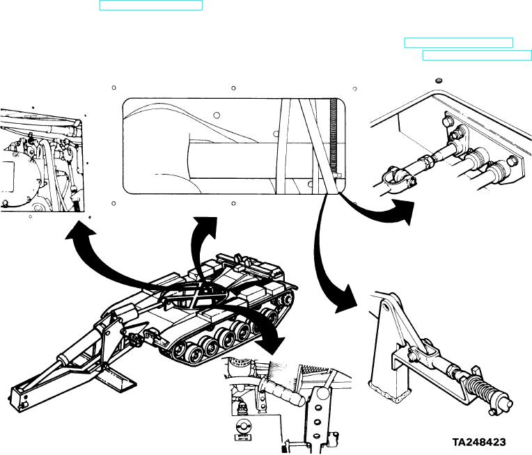
ACCELERATOR LINKAGE ADJUSTMENT (Sheet 1 of 6)
TOOLS: 7/16 in. combination box and open end wrench
1/2 in. combination box and open end wrench (2 required)
9/16 in. combination box and open end wrench (2 required)
Long round nose pliers
Flashlight
FABRICATED
TOOLS:
Throttle linkage adjusting go/no-go gage (Figure
F - 3 , Appendix -F )
SUPPLIES: 1/8 in. dia. by 2 in. by 4 in. long locating pins (2 required)
1/16 in. dia. by 2 in. long pin
Cotter pins (4 required)
P E R S O N N E L : Two
REFERENCE:
Remove operator's floor access plate (page 17-8)
P R E L I M I N A R Y PROCEDURES:
Place shift lever in P (park) position (TM 5-5420-202-10)
Block tracks to prevent tank movement (TM 5-5420-202-10)
Remove upper engine access cover (page 17-11)