
TM
5-5420-202-20-2
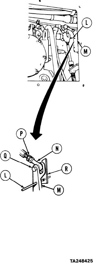
ACCELERATOR LINKAGE ADJUSTMENT (Sheet 3 of 6)
Insert 1/8 inch diameter locating pin (L)
9.
through alinement hole of remote control
lever (M). If locating pin cannot be inserted,
perform steps 10 through 15. If locating
pin can be inserted, skip steps 10 through
15 and go to step 16.
10.
Using 7/16 inch wrench to hold rod end
bearing (N) (on flats), use 1/2 inch
wrench to loosen nut (P).
11.
Using 7/16 inch wrench, remove screw (Q).
12.
Insert locating pin (L) through alinement
hole into housing (R).
NOTE
If rod end bearing (N) cannot be
adjusted short enough for screw
(Q) to slip freely through lever
(M), push rod end bearing (N)
forward and insert screw (Q).
Turn rod end bearing (N) until screw (Q)
13.
slips freely through remote control lever
(M) and rod end bearing (N).
Using 7/16 inch wrench to hold rod end
14.
bearing (N), tighten nut (P).
15.
Using 7/16 inch wrench, tighten screw (Q).
16.
Remove locating pin (L).
Go on to Sheet 4
7-302