
TM
5-5420-202-20-2
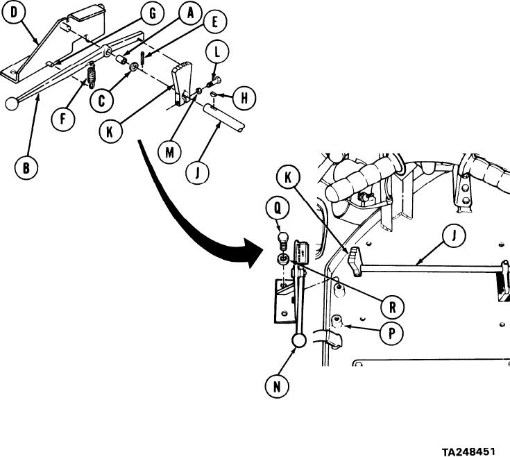
THROTTLE CONTROL HANDLE ASSEMBLY REPLACEMENT (Sheet 3 of 4)
INSTALLATION:
Using vise, press bushing (A) into handle (B).
1.
2.
Install handle (B) and lockwasher (C) to bracket (D).
Using pliers, install cotter pin (E).
3.
Using pliers, install spring (F) onto bracket tab (G).
4.
Insert woodruff key (H) into shaft (J).
5.
6.
Aline segment (K) onto shaft (J). Using
hammer, tap segment (K) lightly to install
segment (K) onto shaft (J).
7.
Using 7/16 inch wrench, install screw (L)
and lockwasher (M) to segment (K)-
8.
Aline the assembled throttle control
handle assembly (N) to segment (K) and
base floor (P).
9.
Using 9/16 inch socket,
install two screws (Q) and lock-
washers (R).
Go on to Sheet 4