
TM 5-5420-202-20-3
MASTER CONTROL PANEL REPAIR (Sheet 31 of 73)
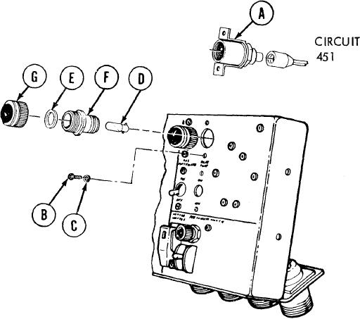
Bilge Pump Switch And Indicator Light Replacement (Sheet 3 of 4)
INSTALLATION:
Using fingers, connect electrical connector (circuit 451) to rear of base assembly (A)
1.
by pushing in.
Place base assembly (A) in
2.
position on panel.
3.
Using screwdriver, install two screws (B) and
lockwashers, (C) securing base assembly (A) to
panel.
4.
Using fingers, install lamp (D) by pushing in
and turning clockwise.
5.
Using fingers, install packing (E) on adapter (F).
6.
Using fingers, install adapter (F) and lens (G)
in position on panel.
TA249009
Go on to Sheet 4