
TM 5-5420-202-20-3
BASKET/CONTROL PANEL ACCESSORIES HARNESS REPLACEMENT (Sheet 4 of 5)
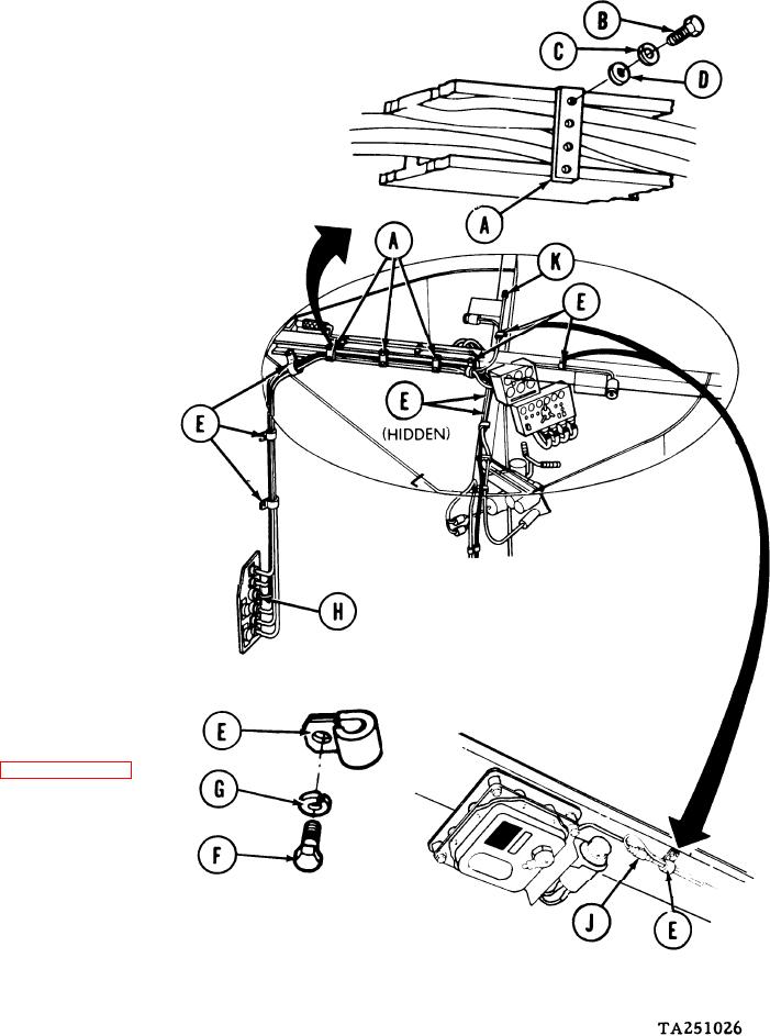
INSTALLATION:
NOTE
The
illustration
below
shows
locations
o f harness assembly
supporting straps and clamps and
the routing of the harness assembly.
1.
Position wiring harness in vehicle.
2.
Position wiring harness
in straps (A) and, using
7/16 inch socket, install
screws (B), new lock-
washers (C), and flat
washers (D) to secure
harness assembly to
overhead crossbeam at
three locations.
3.
Using 7/16 inch socket,
and extension, install clamps
(E), screws (F), and new lock-
washers (G) securing harness
assembly at eight locations.
4.
Install connector
(H) at basket discon-
nect (page 10-296.71).
5.
Connect domelight connector (J) (two places) to domelight resistor lead.
6.
Connect gas particulate connector (K) to gas particulate lead.
Go on to Sheet 5