
TM 5-5420-202-20-3
SHIFTING CONTROL AND RELATED PARTS REPAIR AND REPLACEMENT (Sheet 13 of 14)
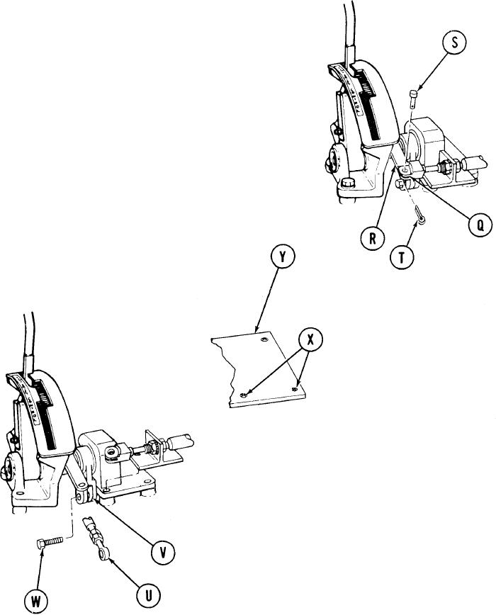
6.
Using socket, extension, and ratchet,
tighten screws installed in steps 3, 4,
and 5, alternately.
NOTE
Make sure that components
are properly alined. If com-
ponents bind, use shims as
required to make sure of
proper alinement and freedom
of movement.
7.
Position brake control clevis (Q) over
brake lever (R).
8.
Install straight pin (S) through clevis
(Q) and lever (R).
Using pliers, install cotter pin (T) in
9.
straight pin (S).
Place rod end (U) in link clevis (V).
10.
11.
Using 9/16 inch wrench, install bolt
(W) securing rod end (U) to link (V).
Using cross-tip screwdriver, install
12.
six screws (X) securing floor plate (Y).
Go on to Sheet 14
TA249281
11-14