
TM 5-5420-202-20-3
SHIFT LINKAGE ADJUSTMENT (Sheet 26 of 28)
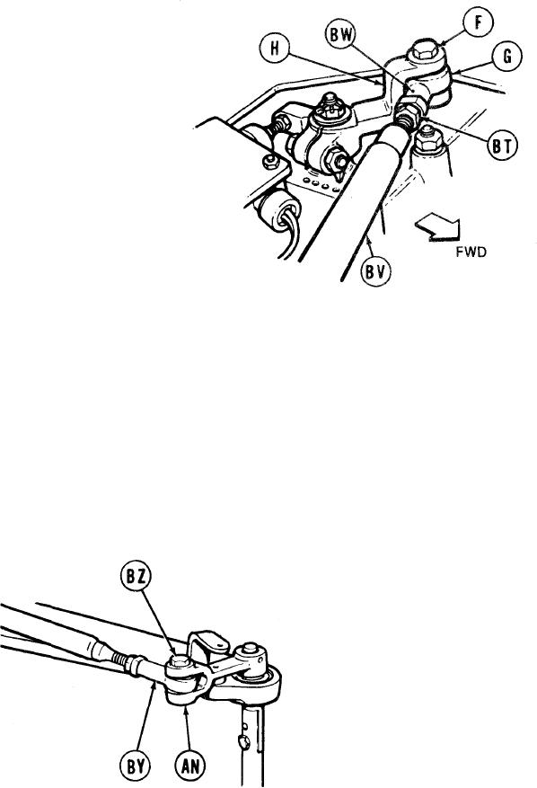
TOP OF TRANSMISSION
Using 9/16 inch wrench, adjust shifting rod
137.
bearing end (G) by turning clockwise until
shifting rod (BV) is past hole (BW).
Using 9/16 inch wrench, remove screw (BZ)
138.
and remove shifting rod bearing end (BY)
from clevis (AN).
139.
Using 9/16 inch wrench, install screw (F)
through clevis (H) and shifting rod bearing
end (G).
140.
Holding rod bearing end (G) with 9/16 inch
wrench, use torque wrench and 9/16 inch
crowfoot adapter to tighten jamnut (BT) to
16-18 lb-ft (22-24 Nm).
141.
Using torque wrench and 9/16 inch socket,
tighten screw (F) to 16-18 lb-ft (22-24 Nm).
RIGHT REAR OF VEHICLE
TA249343
Go on to Sheet 27
11-77