
TM 5-5420-202-20-3
SHIFT LINKAGE ADJUSTMENT (Sheet 24 of 28)
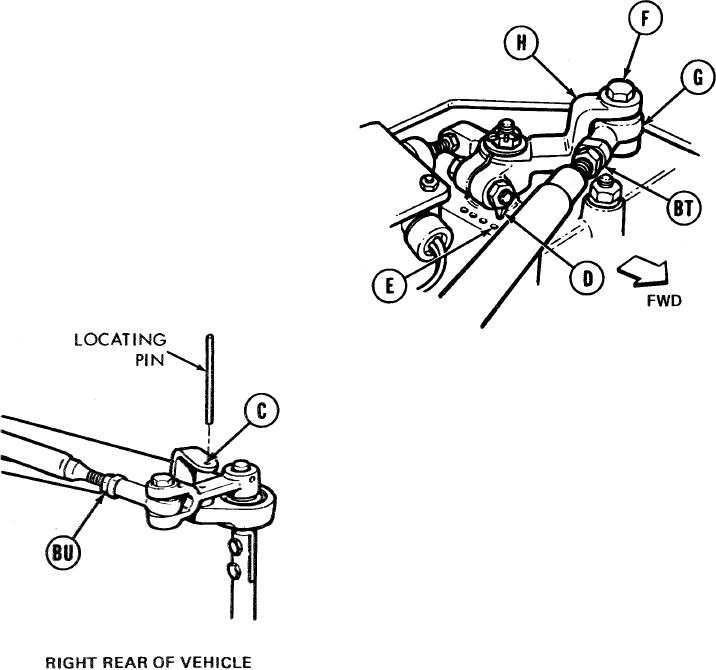
At top of transmission, check position
126.
of shifting position indicator (D). If
shifting position indicator (D) is pointing
to forward most dot (E), linkage is in
adjustment. Go to step 156. If shifting
position indicator (D) is not pointing
to most forward dot (E), go on to step
127.
TOP OF TRANSMISSION
127.
Using 9/16 inch wrench, loosen jamnuts
(BT) and (BU).
128.
Using 9/16 inch wrench, remove screw (F)
if not removed in step 4.
129.
Manually move shifting position indicator
130.
Insert locating pin alinement hole (C), if not inserted in step 125.
NOTE
It may be necessary to move shifting position indicator (D) to rear most dot to adjust shifting rod
bearing end (G) and then back forward most dot (E) to check adjustment in step 131.
Using 9/16 inch wrench, adjust shifting rod bearing end (G) by turning clockwise or counter-
131.
clockwise unitl screw (F) will drop freely through shifting rod bearing end (G) and clevis
(H).
TA249341
Go on to sheet 25
11-75