
TM 5-5420-202-20-3
PARKING BRAKE CONTROL ASSEMBLY (ENGINE COMPARTMENT) REPLACEMENT (Sheet 14 of 15)
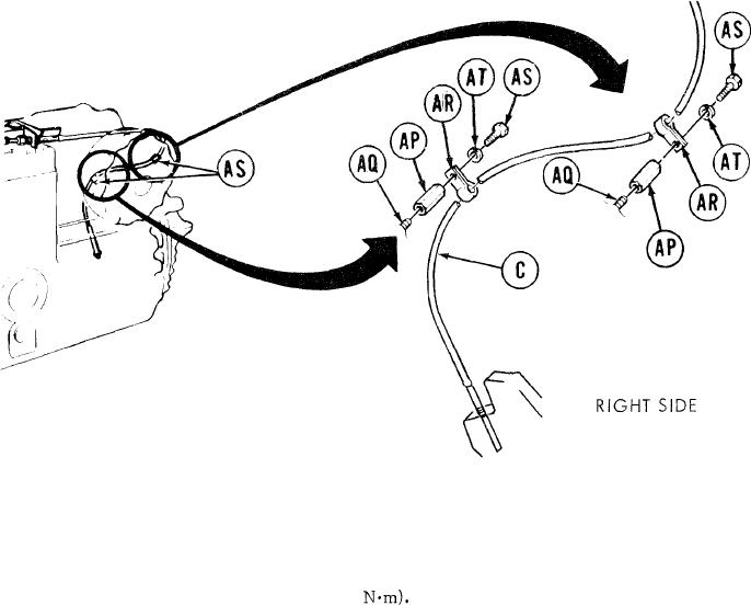
35.
Using 3/4 inch socket, install both spacer nuts (AP) to studs (AQ). Using torque wrench,
tighten nuts (AP) to 54-59 lb-ft (72-80
Using screwdriver to pry open, position clamps (AR) on control assembly (C).
36.
37.
Install screws (AS) and washers (AT) to secure clamps (AR) Using 3/4 inch socket, tighten
screws (AS).
38.
Adjust clamps (AR) to maintain a minimum of 3/4 inch clearance between control assembly
and turbocharger.
TA249504
Go on to Sheet 15
13-120