
TM 5-5420-202-20-3
PARKING BRAKE CONTROL ASSEMBLY (ENGINE COMPARTMENT) REPLACEMENT (Sheet 15 of 15)
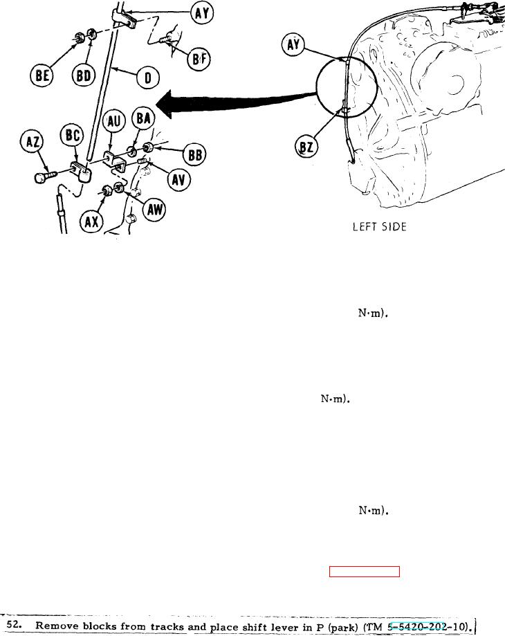
Position bracket (AU) on transmission stud (AV).
39.
40.
Install washer (AW) and nut (AX) to secure bracket (AU). Using 3/4 inch socket, tighten
nu (AX).
41.
Using torque wrench, tighten nut (AX) to 54-59 lb-ft (72-80
42.
Using screwdriver to pry open, install clamp (AY) on control assembly (D).
Install screw (AZ), lockwasher (BA) and nut (BB) to secure clamp (BC) to bracket (AU).
43.
44.
Using 7/16 inch open end wrench to hold nut (BB) and 7/16 inch socket and torque wrench
on screw (AZ), tighten screw (AZ) to 6-8 lb-ft (8-11
Adjust champ (AY) to allow clearance between control assembly and transmission oil filler
45.
tube bracket.
46.
Install washer (BD) and nut (BE) to secure clamp (AY) to stud (BF).
Using 3/4 inch socket, universal joint, and extension, tighten nut (BE).
47.
48.
Using torque wrench, tighten nut (BE) to 54-59 lb-ft (72-80
Adjust clamp to maintain minimum 3/4 inch clearance between control assembly (D)
49.
and turbocharger.
Perform parking brake pawl and bellcrank adjustment (page 13-136).
50.
Install powerplmt (page 5-14).
51.
TA249505
End of Task
13-121