
TM 5-5420-202-20-3
TRACK ASSEMBLY REPLACEMENT (Sheet 9 of 10)
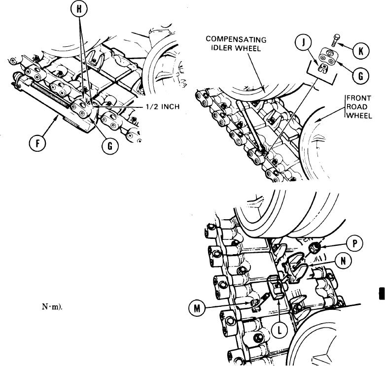
33. Using hammer, drive two end connectors (G)
onto two pins (H) held together by fixture (F)
clamps.
34. Leave 1/2 inch space between end connectors
(G) and fixtures (F).
35.
Remove track connecting fixtures (F).
36.
Using hammer, drive both end connectors (G)
all the way onto link pins (H).
37. Place wedge (J) to underside of end connector
(G).
Using 15/16 inch socket, install bolt (K) through
38.
wedge (J). Tighten bolt snug.
Install cap (L), bolt (M), centerguide (N), and
39.
nut (P).
40.
Using 1-5/16 inch socket and extension, tighten
nut (P) to secure centerguide (N) in place.
41.
Using 1-5/16 inch socket and torque wrench or
torquing tool kit. torque nut (P) to 15-20 lb-ft
(20-27
Go on to Sheet 9.1