
TM 5-5420-202-20-3
TRACK ASSEMBLY REPLACEMENT (Sheet 10 of 10)
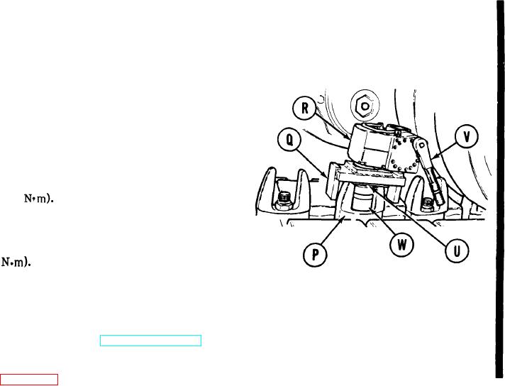
63.
Place 1-5/16 inch socket (W) on drive bar
(U).
64.
Position torque pack (R) with adapter
(Q), drive bar (U), and socket (W) over
centerguide nut (P) to be tightened.
Ensure adapter (Q) legs envelop top of
centerguide ears.
65.
rotate ratchet until socket (W) engages
centerguide nut (P).
66.
Rotate ratchet (V) clockwise until torque
pack dial indicates 350-380 lb-ft (474-
515
67.
Wait approximately 15 seconds, read
dial, and repeat step 66 until dial reading
stabilizes at 350-380 lb-ft (474-515
68.
Rotate ratchet (V) counterclockwise
until dial reading indicates 0. Remove
torque pack.
69.
Apply track tension (TM 5-5420-202-10).
70.
Install rear fender and shield (if required)
End of Task
Change 4 14-88.3