
TM 5-5420-202-20-3
TRACK ASSEMBLY REPLACEMENT (Sheet 9.1 of 10)
NOTE
If track torquing tool kit is available,
go to step 49. If not available, go to
step 42.
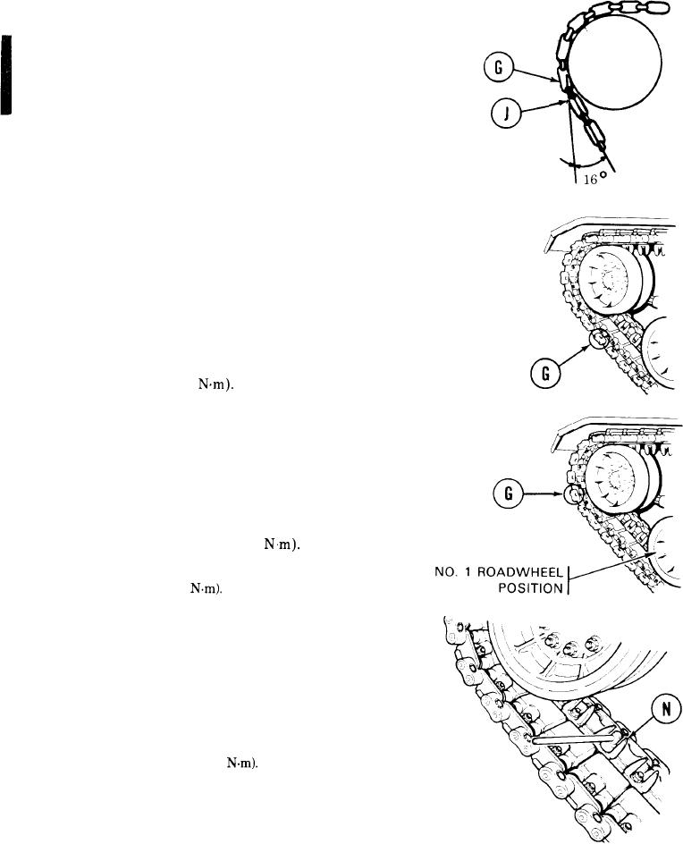
42. Have other person start engine (TM 5-5420-202-
10. Slowly move vehicle until track link in
front of' end connector (G), just installed, is
fully engaged over the compensating idler
wheel and the track link, after end connector
(G) is just touching the compensating idler
wheel.
43. Using torque wrench with 15/16 inch socket,
tighten end connector wedge (J) bolts to
180-200 lb-ft (244-271
44. Move tank until end connector (G) is in lower
position.
45 Move tank until end connector (G) is located in
same position as step 42. Using torque wrench,
tighten to 180-200 lb-ft (244-271
46. Repeat steps 42 thru 44 until torque stays at
180-200 lb-ft (244-271
47. Move tank until centerguide (N) is between
compensating idler wheel and No. 1 roadwheel
position.
48. Using torque wrench, tighten centerguide nut
(F') to 350-380 lb-ft (474-515
Go on to Sheet 9.2