
TM 5-5420-202-20-3
COVER ASSEMBLY (ESCAPE HATCH) ADJUSTMENT (LATE MODEL) (Sheet 1 of 1)
TOOLS: 3/4 in. combination box and open wrench (2 required)
Hydraulic jack
Steel rule
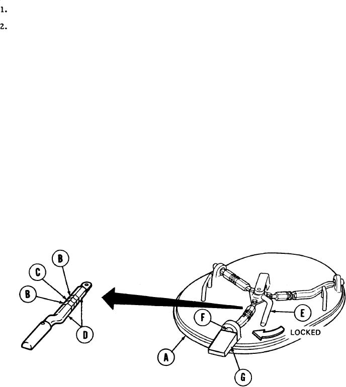
Using jack, position cover assembly (A) on vehicle so that it is seated.
Using wrench, loosen six nuts (B).
NOTE
Turning stud (C) counter clockwise will
screw stud into connectors.
Using wrench, adjust three studs (C) until they are screwed completely into connectors
3.
(D).
Place cover assembly lever (E) in locked position.
4.
Using wrench, adjust three studs (C) until they just start to get tight.
5.
6.
Make sure that bolts (F) are extended over cover assembly lock pads (G) by at least 3/8
inch and there is no space between bolts (F) and pads (G). If there is space between bolts
(F) and pads (G), repeat step 5. If bolts (F) do not extend over pads (G) by at least 3/8
inch, reseat cover assembly (A) on vehicle and repeat complete adjustment.
Using wrench to hold studs (C) and another wrench on nuts (B), tighten nuts (B).
7.
Using heel of foot, move cover lever (E) to unlocked position. If cover lever (E) cannot be
8.
moved to unlocked position, repeat adjustment procedure.
Place cover lever (E) in locked position.
9.
10.
Remove jack.
End of Task
TA249722